Hardware Overview
The LED will light blue when the GPS signal strength is sufficient. This requires a minimum of three GPS satellite connections.
The LED will light blue when the 60 GHz link is ready.
The LED will light blue when the 5 GHz link is ready.
The LED will light steady blue when an active Ethernet connection is made to the Ethernet port and flash when there is activity.
Bootup in progress.
Ready for use, not connected to Ubiquiti® Internet Service Provider (UISP ™ ). See “UISP Management” .
Ready for use, connected to UISP.
Steady Blue with Occasional Flashing
Ready for use, unable to connect to UISP, check connection to UISP server.
Quickly Flashing Blue
Used to locate a device in UISP.
Firmware upgrade in progress.
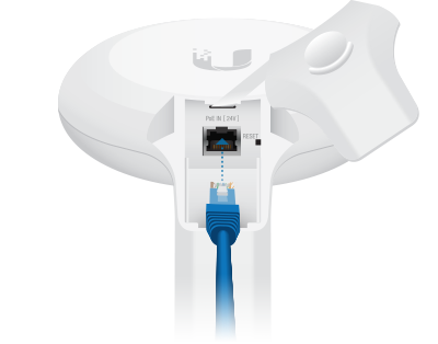
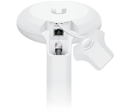
Gigabit Ethernet PoE port for handling all user traffic and powering the device. Default IP address: 192.168.1.20 .
To reset to factory defaults, press and hold the Reset button for more than 10 seconds while the device is powered on. Alternatively, the device may be reset remotely via a Reset button located on the bottom of the Gigabit PoE Adapter.
Installation Overview
We recommend configuring both airFiber radios (Access Point and Station) before site installation. Follow the instructions in “Configuration” for each radio.
Configuration
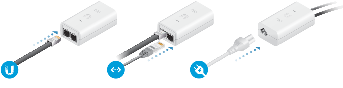
Connecting Power over Ethernet
Configuring the Settings
DHCP
Use one of the following methods:

- Set up the DHCP server to provide a specific IP address to the device based on its MAC address (on the label).
- Let the device obtain an IP address and then check the DHCP server to see which IP address was assigned.
- Launch your web browser. Type the appropriate address in the address field. Press enter (PC) or return (Mac).
- Select your Country and Language . You must agree to the Terms of Use to use the product. Click Continue .
- Enter a Username and Password , confirm the Password , and click Save .
- Click the icon.
- Configure the following settings:
- For one airFiber radio, enable Access Point mode. For the other airFiber radio (the Station), keep Access Point disabled.
- Enter a name in the SSID field. This must be the same on both the AP and the Station.
- In the WPA2 Preshared Key field, enter a combination of alphanumeric characters (0-9, A-Z, or a-z).
 | Note: The key is an alphanumeric password between 8 and 63 characters long. |

Click Save Changes .
Configure each airFiber radio with a unique IP address:
- Click the icon.
- Review the Network settings to ensure that each airFiber radio has a unique IP address. Each can get its IP address via DHCP, or use a static IP address.
- DHCP By default DHCP client is enabled; if there is a DHCP server on your network, the airFiber radio will receive its address via DHCP.
| | Note: If DHCP client fails, the device will use the fallback IP address: 192.168.1.20 |
Fallback IP Address
- Ensure that your computer (or other host machine) is connected to the same LAN as the airFiber radio.
- Configure the Ethernet adapter on your host system with a static IP address on the 192.168.1.x subnet.
- Launch your web browser. Type https://192.168.1.20 in the address field, and press enter (PC) or return (Mac).

- Select your Country and Language . You must agree to the Terms of Use to use the product. Click Continue .
- Enter a Username and Password , confirm the Password , and click Save .
- Click the icon.
- Configure the following settings:
- For one airFiber radio, enable Access Point mode. For the other airFiber radio (the Station), keep Access Point disabled.
- Enter a name in the SSID field. This must be the same on both the AP and the Station.
- In the WPA2 Preshared Key field, enter a combination of alphanumeric characters (0-9, A-Z, or a-z).
| | Note: The key is an alphanumeric password between 8 and 63 characters long. |
- Click Save Changes .
- Configure each airFiber radio with a unique IP address:
- Click the icon.
- Review the Network settings to ensure that each airFiber radio has a unique IP address. Each can get its IP address via DHCP, or use a static IP address.
- DHCP By default DHCP client is enabled; if there is a DHCP server on your network, the airFiber radio will receive its address via DHCP.
- Fallback IP If you use the fallback IP address on one radio, you must change the IP Address setting on the other radio. The fallback IP address is: 192.168.1.20
- Click Save Cha nges .
UISP Management
You can manage your device using UISP, which lets you configure, monitor, upgrade, and back up your devices using a single application. Get started at uisp.ui.com
Installation
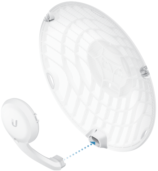
Optional
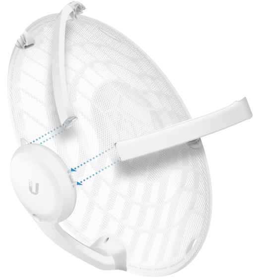
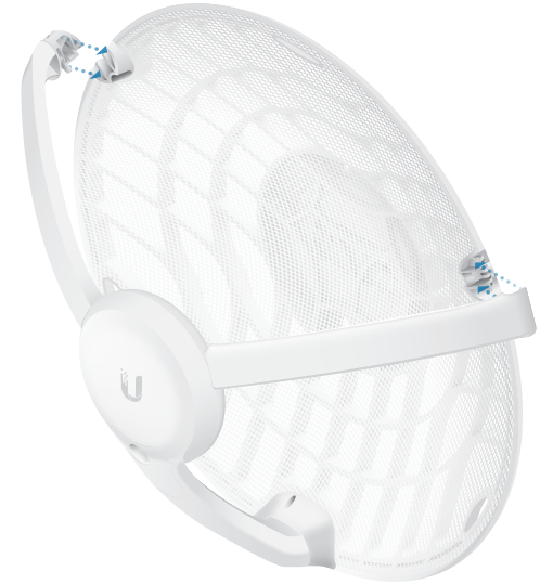
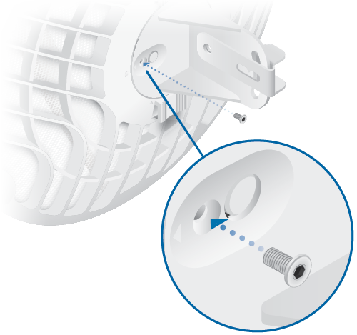
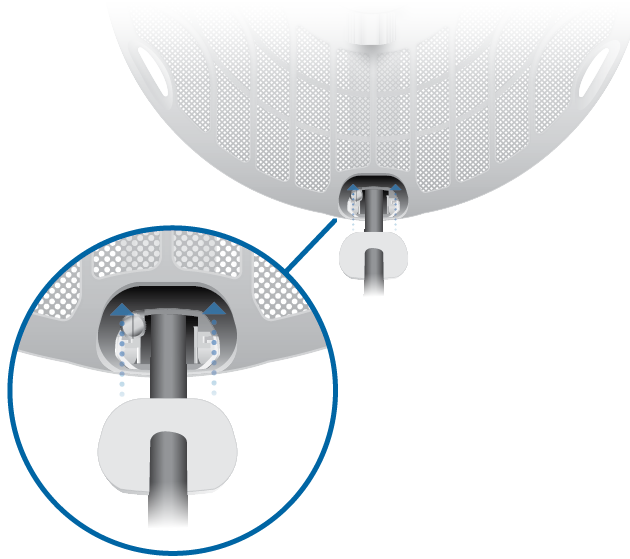
Attach the stabilizer arms for added support.
(This is recommended for long-range installations.)
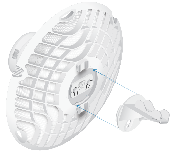
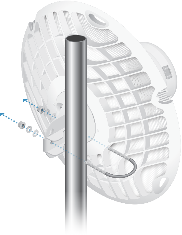
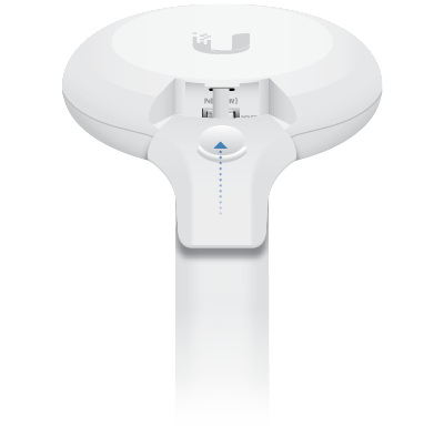
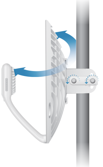
Note: The AF60 can mount on either side of the pole. This section shows the AF60 mounted on the left; the procedure for mounting on the right is similar.
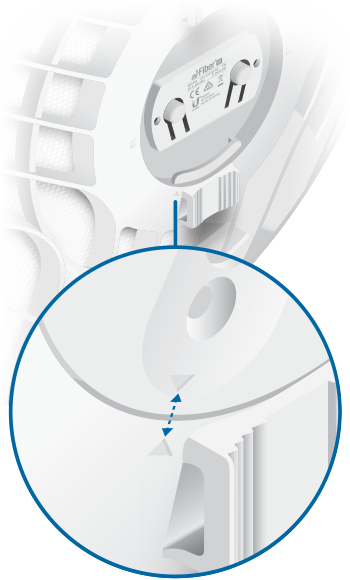
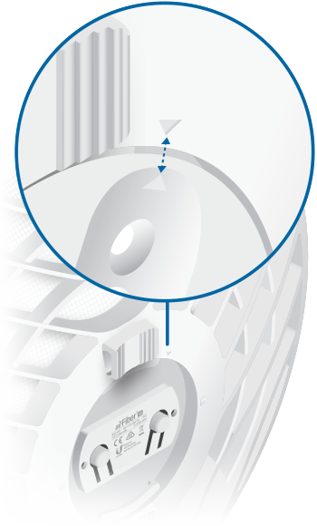
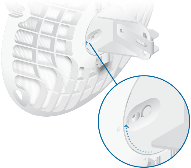
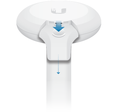
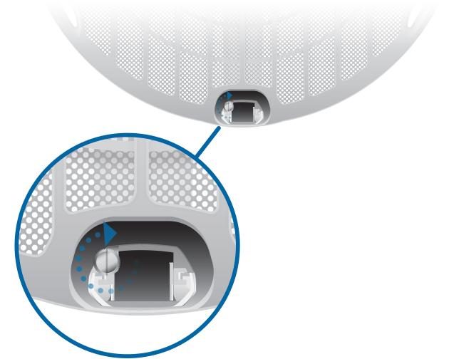
Note: Rotate the Mounting Bracket clockwise until it locks into position.
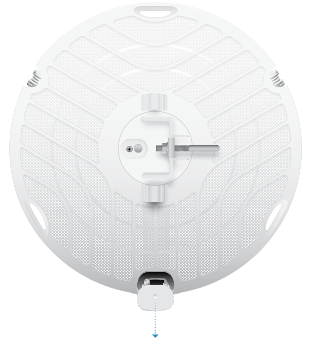
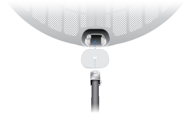
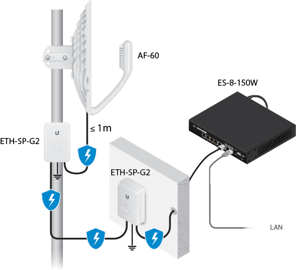
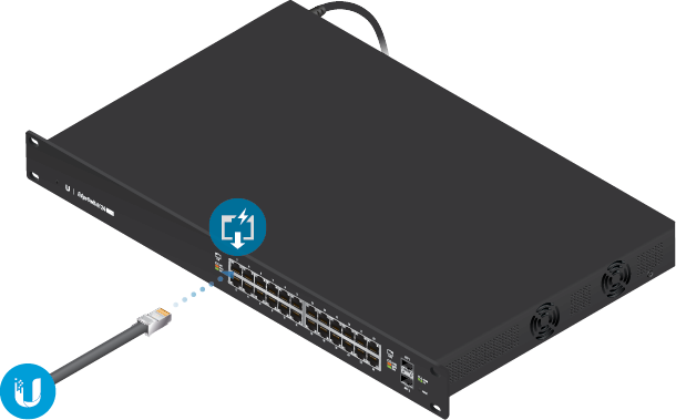
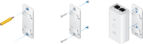
Connecting Power

WARNING: The switch port must comply with the power specifications listed in “Specifications” .
Alignment
Tips
- To accurately align the airFiber radios for best performance, you MUST align only one end of the link at a time.
- You may need to use additional hardware to compensate for issues such as the improper orientation of a mounting pole or significant elevation differences between airFiber radios.
Establishing a Link
Adjust the aim of the AP and the Station to establish a link.
Note: The AP must be aimed first at the Station because the Station does not transmit any RF signal until it detects transmissions from the AP.
- AP Visually aim the AP at the Station by loosening the Flange Nuts on the Mounting Bracket to allow adjustments to the azimuth and the elevation. Adjust the azimuth:
 Adjust the elevation:
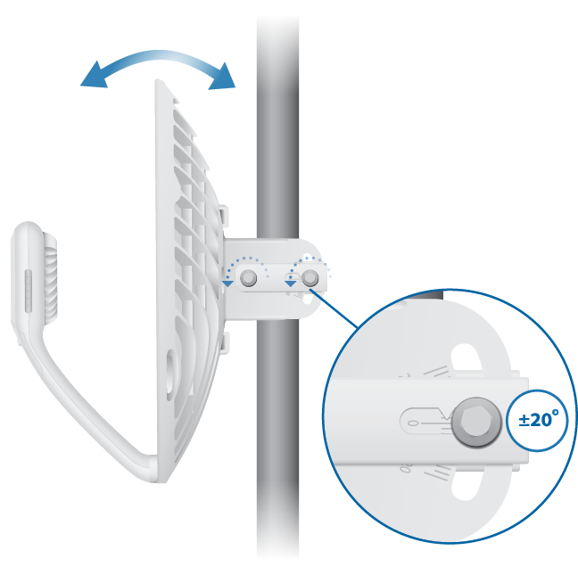
| | Note: Do NOT make simultaneous adjustments on the AP and Station. |
| | Note: Maximum signal strength can best be achieved by iteratively sweeping through both azimuth and elevation. |
Installer Compliance Responsibility
Devices must be professionally installed and it is the professional installer’s responsibility to make sure the device is operated within local country regulatory requirements.
Antenna
The 5GHz Output Power field is provided to the professional installer to assist in meeting regulatory requirements.
Specifications
413 x 413 x 320 mm
(16.26 x 16.26 x 12.60")
Aluminum, UV-stabilized Polycarbonate
(1) 10/100/1000 Mbps Ethernet Port
Max. Power Consumption
Passive PoE, Pins 4, 5+ and 7, 8-
24VDC, 0.5A Gigabit PoE Adapter (Included)
