 Transmitter and Receiver Circuit" width="650" height="369" />
Transmitter and Receiver Circuit" width="650" height="369" />
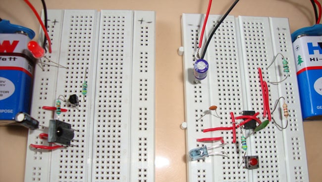
IR Transmitter and IR Receiver are commonly used to control electronic devices wirelessly, mainly through a remote. TV remotes and AC remotes are the best example of IR transmitters. TV generally consists of TSOP1738 as the IR receiver, which senses modulated IR pulses and convert them into electrical signal. Here in our circuit we are building IR remote and its receiver. We are using IR LED as transmitter and TSOP1738 as IR receiver.
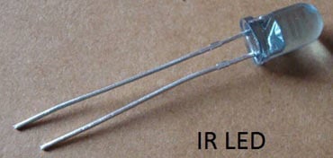
IR LED emits infrared light, means it emits light in the range of Infrared frequency. We cannot see Infrared light through our eyes, they are invisible to human eyes. The wavelength of Infrared (700nm – 1mm) is just beyond the normal visible light. Everything which produce heat, emits infrared like our human body. Infrared have the same properties as visible light, like it can be focused, reflected and polarised like visible light.
Other than emitting invisible infrared light, IR LED looks like a normal LED and also operates like a normal LED, means it consumes 20mA current and 3vots power. IR LEDs have light-emitting angle of approx. 20-60 degree and range of approx. few centimetres to several feets, it depends upon the type of IR transmitter and the manufacturer. Some transmitters have a range in kilometers.
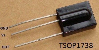
TSOP17XX receives the modulated Infrared waves and changes its output. TSOP is available in many frequency ranges like TSOP1730, TSOP1738, TSOP1740 etc. Last two digits represent the frequency (in Khz) of modulated IR rays, on which TSOP responds. Like for example TSOP1738 reacts when it receives the IR radiation modulated at 38Khz. Means it detects the IR which is switching On and Off at the rate of 38Khz. TSOP’s output is active low, means its output is remains HIGH when there is no IR, and becomes low when it detects IR radiation. TSOP operates on particular frequency so that other IRs in the environment can’t interfere, except the modulated IR of particular frequency. It has three pins, Ground, Vs (power), and OUTPUT PIN.
We are using TSOP1738 as IR receiver, so we need to generate the modulated IR of 38 kHz. You can use any TSOP, but you need to generate IR of respective frequency as TSOP. So we are using 555 timer in Astable mode to oscillate the IR at 38KHz frequency. As we know oscillation frequency of 555 timer is decided by resistor R1, R2 and capacitor C1. As you can see in the blow IR Transmitter Circuit We have used 1k R1, 20K R2 and 1nF capacitor to generate the frequency of approx. 38 KHz. It can be calculated using this formula: 1.44/((R1+2*R2)*C1).
Output Pin 3 of the 555 Timer IC has been connected to IR LED using 470 resistor and a push button switch. Whenever we press the button, circuit emits modulated IR at 38 KHz. A 100uF capacitor is connected across the supply to provide the constant supply to the circuit, without any ripple.
IR Receiver circuit is very simple we just need to connect a LED to the output of the TSOP1738, to test the receiver. We have use BC557 PNP transistor here, to reverse the effect of TSOP, means whenever the output is HIGH LED will be OFF and whenever it detects IR and output is low, LED will be ON. PNP transistor behaves opposite to the NPN transistor, it acts as open switch when a voltage applied to its base and acts as closed switch when there is no voltage at its base. So normally TSOP output remains HIGH and Transistor behaves as open switch and LED will be OFF. As soon as TSOP detects Infrared, its output becomes low and transistor behaves as closed switch and LED will be ON. As you can see in the below IR receiver circuit A 10k resistor is used for provide proper biasing to transistor and a 470ohm resistor is used at LED for limiting the current. So whenever we press the Button at IR transmitter, it is detected by TSOP1738 and LED will glow.
We have further modified this circuit by using a relay to operate the AC mains appliances by an IR remote, in this remote controlled switch circuit. Check out our electronic circuits section to learn and build more interesting circuits and simple projects.